
Filling & Capping
Combined filling and capping solutions (integrated systems and complete lines).
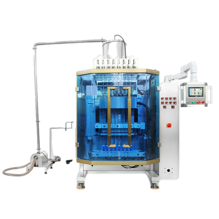
Integrated filler-capper specification and handover
Define dosing, cap handling, controls and changeover as one operating sequence
Map the container through every controlled position
An integrated filling and capping machine combines operations that are often tested separately, so the interface between them must be made explicit. A typical indexed system may include an inlet conveyor, container gating or an indexing turntable, filling pumps and nozzles, cap handling devices, a capping head and an outfeed conveyor. The exact mechanical build, number of filling channels, cap presentation method, change parts and guarding depend on the product, container and closure supplied for the project.
Start by defining how an empty container is detected and positioned, how the fill cycle is authorised, how the cap is presented, how the closure is tightened and how the finished pack is released. Bottle-present, cap-present, drive-status, emergency-stop and other interlock signals should have a clear purpose. The machine should not depend on an operator correcting inconsistent presentation between the filling and capping stations.
| Process stage | What to verify | Evidence for handover |
|---|---|---|
| Container infeed and indexing | Stable entry, correct spacing, positive location and recovery after a gap or stop. | Format settings, guide positions and safe clearing method. |
| Filling setup | Correct product path, nozzle position, enabled channels, fill setting and controlled start and stop. | Calibration record using production product and representative containers. |
| Cap handling | Orientation, delivery, cap-present detection and removal of a misfed closure. | Approved samples and documented feeder or manual-placement setup. |
| Capping | Initial engagement, bottle stability, tightening setting and finished closure condition. | Agreed torque or closure-integrity check and accepted sample set. |
| Discharge and downstream interface | Release without marking, tipping or back pressure and correct hand-off to the next operation. | Conveyor settings, interface signals and accumulation limits. |
Calibrate with the real product and format
Lancing operating documentation for the LU-AFC28 filling and capping platform describes individual pump enable, preset fill volume, filling speed, pump jog, single-injection testing and entry of the measured actual volume for calibration. The documented procedure uses the correct production product, bottle and nozzle, measures a test fill and repeats the adjustment for each enabled channel. It also notes that viscosity, temperature, foaming and nozzle condition can affect the filling result. These principles apply more widely: the commissioning method must state the product condition, measurement method and accepted result rather than relying only on a stored recipe value.
For capping, the same documentation separates tightening speed, torque setting and displayed motor torque. The closure should be checked for loose application, over-tightening, damage and cross-threading, using the customer’s approved method. The machine setting is a process parameter; it is not a substitute for confirming the finished closure on representative bottles and caps.
Plan changeover, cleaning and fault recovery
Each format needs a documented route for guides, nozzles, container holders, cap tooling, feeder settings and recipes. Product-contact parts should be accessible for the agreed cleaning method, while cap handling and the indexed mechanism need safe access for inspection and clearing. Manual functions should be reserved for setting, testing and fault finding, with personnel kept clear of moving conveyors, turntables, pneumatic devices and capping mechanisms.
For a quotation or sample trial, provide product and safety information, bottles and closures, fill range, changeover matrix, required closure check, cleaning routine, available utilities, site layout and any downstream labelling, sealing or conveyor interfaces. Separate filling and capping machines may be more suitable where the two operations need different speeds, independent cleaning, substantial accumulation or future layout flexibility. Review the integrated system range and include commissioning, training, documentation and spares in the project scope.
Integrated filling and capping planning resources
Extend the existing system guidance into line interfaces, trials and pack applications
The integrated sequence should be tested with the complete product, bottle and closure combination. Use the bottle application to include empty-container handling, neck cleanliness, downstream labelling and accumulation.
The integration guide adds ready/fault states, controlled stops and transfers, while the trial guide turns fill and closure requirements into repeatable evidence.
Where short campaigns or incompatible cleaning requirements make an integrated platform restrictive, compare separate machines and the accumulation required between them.
Integrated-system evidence
- Production product, bottle and closure
- Fill and closure acceptance methods
- Format and changeover matrix
- Product and cap feed method
- Stop, clear and restart sequence
- Downstream interface
- Commissioning and training scope